Problems at the Marking up stage at the rig and the core yard
Okay, just because you have sailed successfully past the potential problems associated with orienting the core doesn't mean you should get complacent. Unfortunately, there are still a lot of issues to be aware of. This post looks at a few of the relatively more common problems but it is by no means exhaustive.
On your mark – lining up for inspection
Since each orientation mark has an unknown accuracy, it can only be accepted if it correlates with one, and preferably two or more, of the other adjacent orientation marks. That is, a straight line must connect the orientation marks when coherent core between the marks is confidently reassembled (Figure 1).
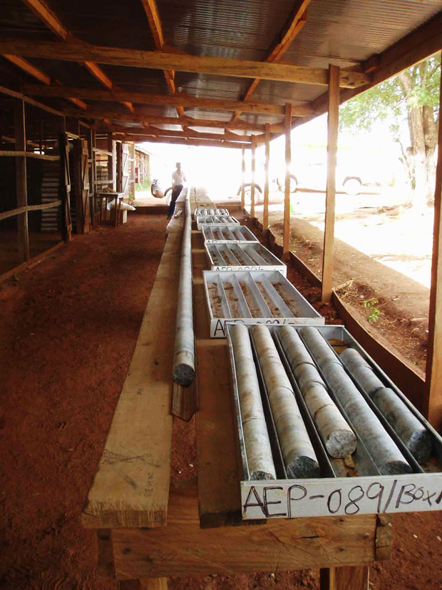
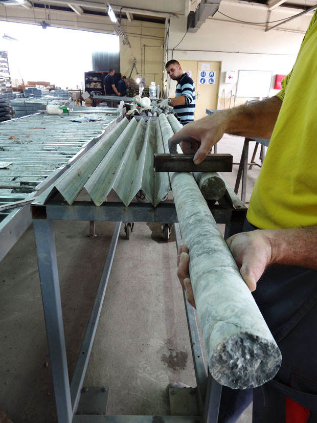 Figure 1 – The top photos shows core laid out in a piece of angle iron to the left of the trays it was taken from. The oriented marks are then lined up and the edge of the angle iron used as a guide to draw the orientation line. The bottom photo shows a sheet of iron with angular corrugations that hold the core. The orientation marks are aligned on the top side of the core (still bottom of hole but the core is rotated around). A piece of iron is then rubbed against the core and produces a non-temporary line on pieces of adjacent core. This line can then be checked against the marks for consistency and over-written in ink if the marks are of good quality.
By drawing a line along the bottom of the core, which joins the individual bottom-of-hole marks, we are able to provide an “orientation line” from which the true orientation of the planar and linear structures in the drill core can be determined. The accuracy of the orientation line is critical to the quality of the orientation measurements. If the orientation line is not correct all measurement made relative to the line are inaccurate and the data collected will be incorrect and misleading.
To make an orientation line the core should be reconstructed between the orientation marks in a V-rail (angle-iron) that is at least several runs long. For example, if using a 6 metre core barrel then at least 20 metres of angle iron should be available to lay the core out on. This allows three marks to be assessed for consistent, bottom-of-hole positions as well as incorporating portions of core from intervals above and below that selected. Alternatives to this include the use of a sheet of corrugated or ribbed metal that allow successive runs to be lined up adjacent to each other (Figure 1).
Prior to marking the orientation line the core must be carefully reassembled (Figure 2).
This may require gluing together of core fragments in critical areas. Every break must be carefully inspected to assess its validity in terms of coherent joins. Failure to do so will result in misaligned core and an inaccurate line (Figure 3).
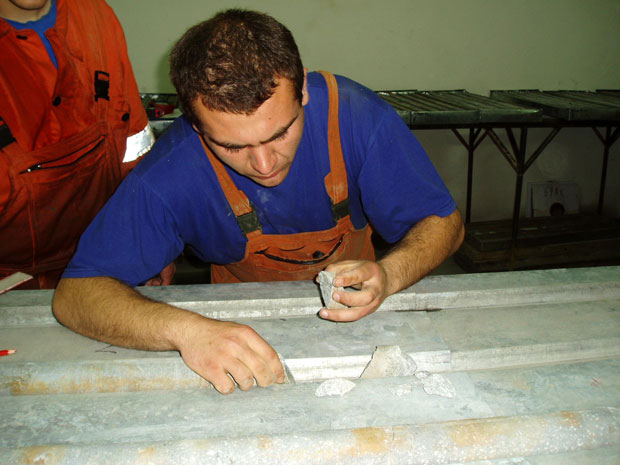 Figure 2 – If it is critical to get an orientation from intervals of broken core careful reassembly is required, commonly by gluing the pieces of core back together.
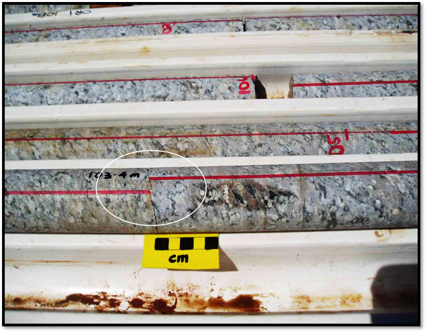 Figure 3 – The core either side of the angled break (circled) fits together tightly. There is a lack of quality control associated with the red orientation line, however, as it shows misalignment across the break. The core across the breaks had not be pushed together to check the joins prior to marking. As an aside, this mistake was noted while arguing with a geologist who adamantly asserted that there were no core orientation issues.
A common occurrence in drill holes that traverse markedly different rock types, or that contain thin ductile shear zones, is core-spin. If an interval of core becomes free spinning it may show a tight join across one or both ends of the interval. This is because the core is ground into the next interval across the break. Consequently, many apparently tight joins are the result of drill-induced grinding and the orientation line cannot, and should not, be carried across these. This is easily identifiable when all the breaks are examined because the core will have concentric rings on the broken face (Figure 4) and the join will be at right angles to the core. Taking measurements from rotated core will give data distributions like that shown in Figure 5.
As a general point of interest, the rotation of drill rods during coring is typically clockwise. Consequently, rotation about the drill hole axis will likewise be clockwise. However, there is no way of determining how many times the core has been rotated or how far (e.g. a rotation of 20 degrees will be the same as a rotation of 380 degrees).
It is important to check for continuity, or otherwise, of geological markers (e.g. veins) across the break. If the marker is displaced across the join then the orientation line should not be carried across the break. Likewise, if the marker is continuous across the break but the orientation line is displaced there is a problem, usually with your staff! Unacceptable situations like that in Figure 6 result from a lack of diligence on the part of the geologist.
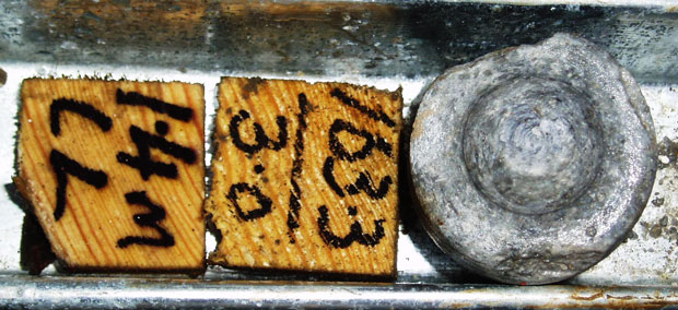
 Figure 4. Examples of core spin that have induced circular marks on the core either side of the break.
 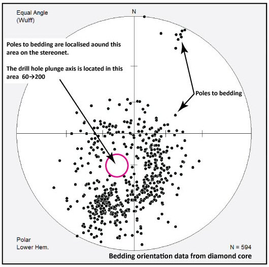 Figure 5. Example of a small circle distribution of data due to measurements being taken from core that has been rotated.
 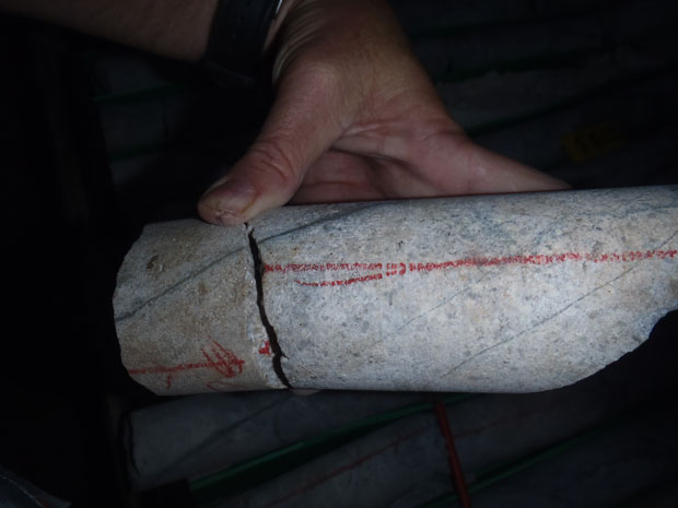 Figure 6. Poor geological practice exemplified by misalignment of a core orientation line across a core break. Note that the core fits together well and when it does the pyritic vein under the thumb is continuous.
The orientation line may be extended up to several metres past the last orientation mark provided that the core can be confidently reconstructed. The points at which an orientation line is stopped and the reason for the termination should be recorded on the orientation record form. In extreme situations where orientations are critical, a single reference line may be extended for many tens of metres in competent well-oriented core, although this is not advisable. The opposing situation has also been encountered where the lack of training of geologist and technicians resulted in orientation lines terminating at the ends of the core runs despite continuity of good core.
The correct way to position core in V-rail is with orientation mark parallel to edge with a pen held horizontal to the edge of the V-rail. The pen should be kept horizontal when drawing the reference line. It cannot be stressed how important it is that the pen be kept horizontal. The tendency is to roll the wrist as the mark is put on the core but this can cause a progressive deflection of the orientation line from what it should be. The ultimate result will be an orientation line that spirals around the core! Unfortunately, the spiralling line may only be evident if a substantial portion of the hole is laid out. Data from this situation will appear rotated because a consistently changing line orientation is used as the reference when taking alpha-beta measurements or measuring directly from dill core.
Different line types, or colours, should be used to delineate between lines of high confidence and those where there is some uncertainty as to the quality of the line (Figure 7). Another line type or colour should be used to mark a ‘cut’ line along which the core is sectioned for sampling. It might seem obvious, although a number of site visits have proved otherwise, but the geologists, technicians and people cutting the core should all be familiar with the different line types. It is quite maddening to ask geologists, who supposedly know about a deposit, and find that they can’t tell you which is the orientation line and which is the ‘cut’ line. It is even more frustrating to find that the guy cutting the core doesn’t know which line is which and has removed the orientation line! There is little hope of rectifying this as the line has either been lost when it was sawed or it is somewhere in a sample bag.
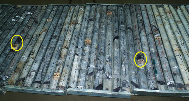
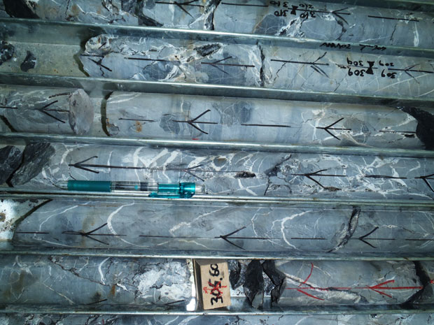 Figure 7. Different line styles showing different levels in confidence of the orientation marks used to construct them. Continuous red lines are good quality, broken black lines poor quality. Arrows point in the down-hole direction. Note that line colour changes across core breaks where core continuity has been lost. The bottom figure shows the break causing loss of orientation at the right hand yellow circle in the top figure.
Comments on convention
Line marking on core should always show the down-hole direction of the hole as an arrow (Figure 7). This convention applies to cut lines as well as orientation lines and helps avoid core being placed back into the trays the wrong way round. Unfortunately, society today favours idiots and people who can’t think for themselves. As a result, I have seen holes with the arrows pointing up-hole and, in a couple of cases, intervals of core where the arrows at either end of the intervals pointed both up- and down-hole.
When placing an orientation line on the core the industry convention is to use the line that connects the bottom-of-hole marks. Unfortunately, there are uncommon situations where the line gets transferred to the top of the core. The problems created are two-fold. Firstly, error in the line position is induced during the process of transferring from the bottom of core to the top of the core. Secondly, if the geologist is not made aware of the non-industry procedure of swapping the line from bottom of core to the top, he/she will place the core in an orienting frame in a position that is rotated 180 degrees from its true orientation. Similarly, the use of kenometers and alpha-beta strips is typically done relative to a bottom-of-core line, not top-of-core.
You may think the situation above is uncommon but I have seen it on several occasions. I experienced an even more ridiculous situation where I worked on the initial holes into the Wallaby deposit in the Eastern Goldfields of Western Australia. After spending a day or so in the balmy 40+ degree summer heat in the core yard I felt that the data was not making sense. When I queried the resident exploration manager about the core orientations he said ‘oh, didn’t we tell you?! Joe Bloe (real name suppressed) wanted to view the orientation line when he was looking at the core so he changed it from the bottom of the core to the top of the core after the first seven holes’. This is a ludicrous and unacceptable practice and any geologist doing it should be taken out into the core yard and rolled in the bindies! Or beaten! Or both!
Methods of measurement and comments on interpretation
Collection of data is principally done directly via measurement in core orienting frames, or indirectly by taking alpha and beta and gamma readings and then calculating true orientations via a spreadsheet or some form of canned software.
Numerous forms of core orientation frame are available, from commercially produced ones to those that have been manufactured on-site. All of these will work well although care has to be taken that they are made entirely of non-magnetic material! Failure to do so can produce some interesting (erroneous!) results. Figure 8 shows the impact of magnetic material in a core orienting frame.
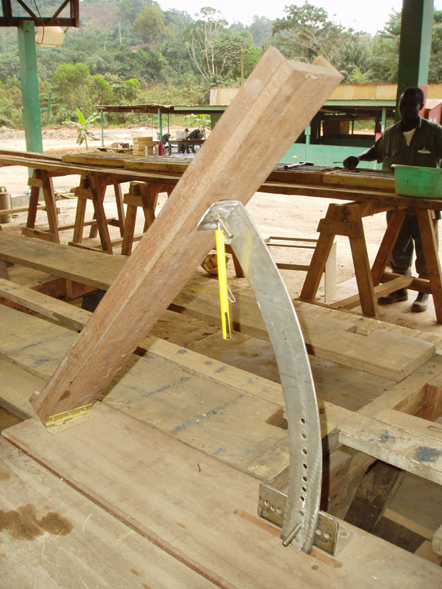
 Figure 8. Examples of problems arising from a core frame that contains magnetic material (top figure). The yellow item is a pen magnetic. The needle orientation in the compass at the bottom of the figure shows that measurement can be out by as much as 30 degrees, depending on proximity to the core frame.
In the case of alpha and beta measurements the introduction of the Kenometer has been extremely useful. Regardless of the method used for taking alpha and beta measurements, it is recommended that a core frame/rocket launcher is used for the measurement of structures in oriented core at the start of each individual project.
The use of a core orienting frame permits direct visualization of the structures in their original orientations. In some cases this can help avoid some very embarrassing and even more expensive errors. I worked on a job in West Africa where a deposit was proceeding to the resource evaluation stage. All of the measurements of the structures, including the planar mineralised zones, had been taken using the alpha-beta method. Interpreted drill section showed beautiful, subvertical gold-bearing zones. When I checked the orientations using a core frame it turned out that that the mineralised zones were actually subhorizontal. A lot of the problem centred on geologists who didn’t want to leave their air-conditioned offices to spend time in the icky, humid core yard.
If a considerable amount of data is required quickly, the alpha-beta-gamma method can be used. If using the alpha-beta-gamma method, I will reiterate what I said above and say it is a good idea to also have a core frame so that structures can be visualized. Core frames allow measurement of non-penetrative linear features and checks on the alpha-beta-gamma measurements taken from the same intervals.
I have seen examples where a lot of alpha and beta data has been collected but the geologist never used a core orienting frame to double check measurements or to visually assess the structural relationships. It never ceases to amaze me when I see a lot of widely varying alpha and beta bedding data but the core in the trays shows a consistent core to bedding angle.
Over-reliance on software – taking interpretations too far
Figure 9 below is from a project where the client assured us that their bedding orientation data was impeccable. Note that this is the same data as shown in Figure 5. The data distribution for poles to bedding should have rung some very loud alarm bells. The plots also highlight some of the pitfalls of letting software deal with the data. In the upper figure the individual data are plotted and they form a distribution that defines a broad circle with an area of minimal data in the core of the distribution. This is a typical distribution for data that has been rotated and is referred to as a small circle data distribution. The axis of rotation is the drill hole orientation. From this plot alone it is possible to predict that the drill hole orientation was approximately 60→200.
The bottom figure shows the problems that can arise if results from contouring software are allowed to dominate the interpretation. Instead of the obvious small circle distribution we now see two maxima that are interpreted as the poles to two dominant bedding orientations, which are shown as the great circles representing planes 1 and 2. Interpretation can be extended even further by inferring that the two planes represent the opposing limbs of a fold and that the intersection of the planes is the fold axis. Consequently, we have erroneously inferred two dominant bedding orientations, and the orientation of a fold axis, even though the upper figure shows that the data are clearly rotated about the drill hole axis (best-fit small circle of all bedding poles shown in dashed blue line).
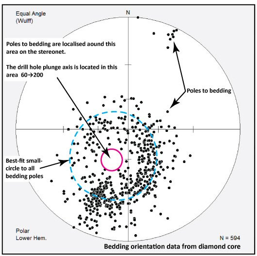
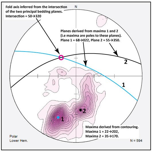 Figure 9. A plot of individual orientations for bedding is given in the top figure and clearly shows a small circle distribution. The centre of this distribution is the rotation axis, which is the orientation of the drill hole axis. The bottom figure shows computer-generated contours of the same data, which gives two dominant orientations. Based on this, erroneous interpretations regarding overall bedding geometries and deformation events can be made.
Finally, do not wait till a drilling program is over before you start orienting the core, taking measurements, or performing checks. Once the program is over it may be too late, especially if all the critical data is of low confidence. You may not have the money, logistical support, or support of management if you go cap-in-hand to them and say ‘please sir/madam, I have stuffed up. All of the orientations we paid for and all of the data we collected are rubbish. I need to redrill the holes’. At the very least, you will get beaten about the head with a foam whiffle bat. At worst, your reputation, your performance review and your contribution to future exploration programs will suffer.
I will make the following plea, although I know it will be ignored more often than I want to hear about. Please, start checking core orientations, core integrity, confidence in orientation marks, and data distributions from the start of the program. You need to identify problems early. Getting Orefind or some other consultant in at the end of a program will simply frustrate us because there is commonly no way to recover the data collection campaign – it will be too late.
Concluding comments
As stressed in the previous posts comprising my contributions on drill core orientations, the geologists must take ownership of core orientation and data collection. They should not simply trust the drillers and the geotechs further down the line to get it right! Get out of your comfy chair and climate-controlled office and go and look at the rocks.
Never, ever assume the core is correctly oriented. Perform some checks e.g. measure a feature that has a consistent orientation regionally and check that it conforms.
A “rocket launcher” should be used initially for oriented core at the start of each project and regularly throughout the logging process. This permits direct visualization of the structures. A rocket launcher should always be on hand for check measurements, and for measuring non-penetrative linear features (e.g. fold hinges).
If a large amount of data is required, the alpha-beta-gamma method should be used. Use of equipment such as the Kenometer can facilitate this. However, regular checks should be made using a core orienting frame.
A number of core orientation methods are available and the industry is still achieving a broadly accepted standard, which will likely be either the Reflex™ tool method or the Ezy-Mark™ method. Those methods with more than one independent check on orientation, and those with the least number of moving/mechanical parts, will become most widely used.
Modest amounts of good quality, from well-oriented drill-core, data are much better than large amounts of poor quality data.
A geological history that combines paragenetic and deformation histories is an essential framework to constrain geometric relationships gathered from oriented core. This will be a discussion for a future blog.