As covered by Jun Cowan in June this year in his post
Six reasons why Micromine’s new implicit modelling software could triumph over Leapfrog, Micromine has recently brought out an RBF-based implicit modelling module. Unlike some other packages – such as
Geovia’s Dynamic Shells, this is a true implicit modelling method. I have had the pleasure of putting it through its paces lately and found it is quite a capable module. The menu shown below contains the various options available (Figure 1);
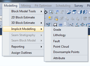 Figure 1. Micromine’s menu to access the Implicit Modelling commands.
The menu items are relatively self-explanatory. The first two options run from a drillhole database.
Grade allows you to model grade shells at specific cut-offs, of course Grade covers any form of numerical modelling and can be used for grade, metal ratios, contamination, DH meter drill rates (great for modelling broken ground!), etc.
Lithology, of course is for modelling lithology – rocktypes, oxidation, alteration or any other alphanumeric classification. It allows you to include, exclude and ignore various codes just as you can in Leapfrog for building a sequenced geological model (exclude older – ignore younger lithologies). Using this option also allows you to generate a flagged point table based on the drilling that contains the interpolated values, this file can be edited using additional points or lines and modelled using the
Attribute menu item to refine your output.
Fault models faults using a surface trace with dip and dip direction and can also use an additional file that contains structural dip and dip direction measurements that may be taken down holes. As it works on these two basic structural elements it can be used to model any 2D surface, bedding traces, unconformities, etc for which you have measurements available.
Point Cloud is for modelling anything with a series of points that define a surface, this surface can be open – such as a topographical surface or a closed surface such as a stope or scan.
Downsample Points uses a mesh (grid) size to reduce the number of points in a file, very useful for reducing the number of points in a Lidar Topographic survey to something approaching a manageable size. Finally the
Attribute option allows you to model any file with +ve or -ve values, more specifically the output interpolated file from the lithology modelling option. After editing the interpolated file with a few extra points with positive and negative values to define additional contact points you use the Attribute option to generate a shell at 0 value and you can replicate the Lithology shell.
Unlike Leapfrog which has both global and local estimators, Micromine’s method only uses a local estimator and as a result the local domain must first be defined when setting up the interpolation. This is done by selecting the
Max points per Partition, Micromine suggests a starting point of approximately 1/8th the number of samples you are modelling, I have found this to be a good starting point and then I make some adjustments and observe the results. The Point Cloud option is bit different as you have to decide on two numbers, the
Number of Neighbours – used to determine the surface orientation and what is top or bottom (inside/outside) of the surface, and the
Max Points per Neighbour, the numbers used here are dependent upon the type of surface you are modelling and the complexity and density of the points. You may use smaller figures for complex surfaces with lots of points or closed wireframes (such as a tunnel or stope), or larger figures for less dense, less complex surfaces, such as topography. Using too many points per neighbour for complex curved surfaces will interfere with Micromine’s ability to model the curves and turns. I refer you to the Micromine Help files for more information on how to go about this.
So what about the results? I have taken the tutorial datasets from both Micromine and Leapfrog and run them through both programs. Below I present some comparisons between Leapfrog (using Leapfrog Mining, but Leapfrog Geo outputs the same result) and Micromine.
Figure 2 shows the results of a basic Isotropic search of the copper variable from Leapfrog’s Marvin dataset. Whilst there are some very slight differences that relate to the different interpolation methods, the results are remarkably similar.

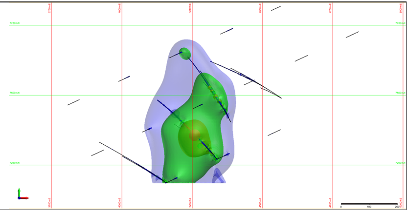
Figure 2. Isotropic search on copper from the Leapfrog Marvin dataset. Leapfrog model shown on top and Micromine, below.
Figure 3 shows the results of using the Lithology modelling. Here I have modelled the QzP rocktype from the Marvin Dataset. The final output shows a close similarity between the two. In order to complete the Micromine surface I have had to add a couple of additional points on the surface trace and then remodel the wireframe using the attribute modelling option.
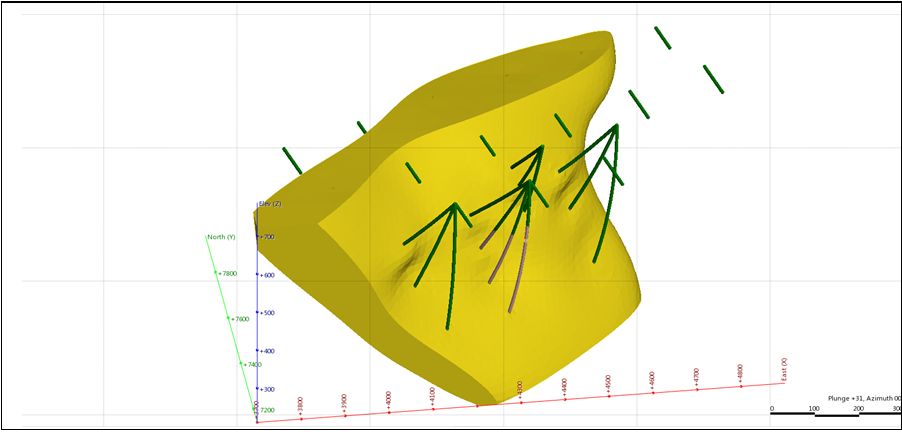
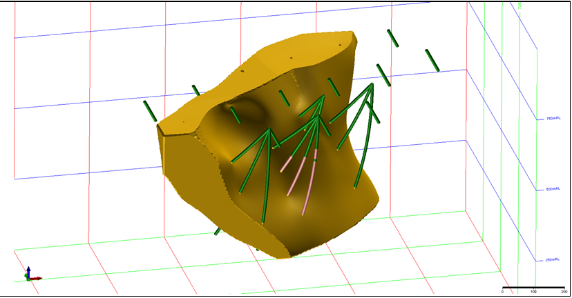 Figure 3. QzP wireframe of the Leapfrog Marvin dataset with Leapfrog model shown on top and Micromine, below.
Figure 4 shows the results of modelling the global 5ppm gold grade shell from Micromine’s NVG dataset using the same anisotropy, again there is little to differentiate the results.
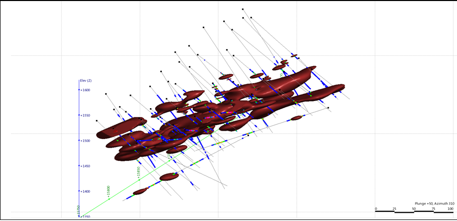
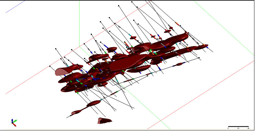 Figure 4. 5gpt shell from the Micromine NVG dataset with Leapfrog model shown on top and Micromine, below.
Figure 5 shows the results of a largely unguided lithology interpolation of one of the NVG veins, the results from both programs is unacceptable. Whilst I have used an anisotropy for the search both programs have failed to adequately model the vein.

 Figure 5. Unguided vein interpolant of a single vein from the Micromine NVG dataset with Leapfrog model shown on top and Micromine, below.
Figure 6 however, shows the results using a little bit more thought and guidance. The Leapfrog surface uses a drill hole interval selection and the vein modelling methods to drive the interpolation, the resulting output is much better. With Micromine I have extracted the footwall and hangingwall points for the vein from the drilling and used the point cloud option to model the footwall and hangingwall surfaces. I have then used the wireframe solid from surfaces option to create the solid volume of the wireframe.
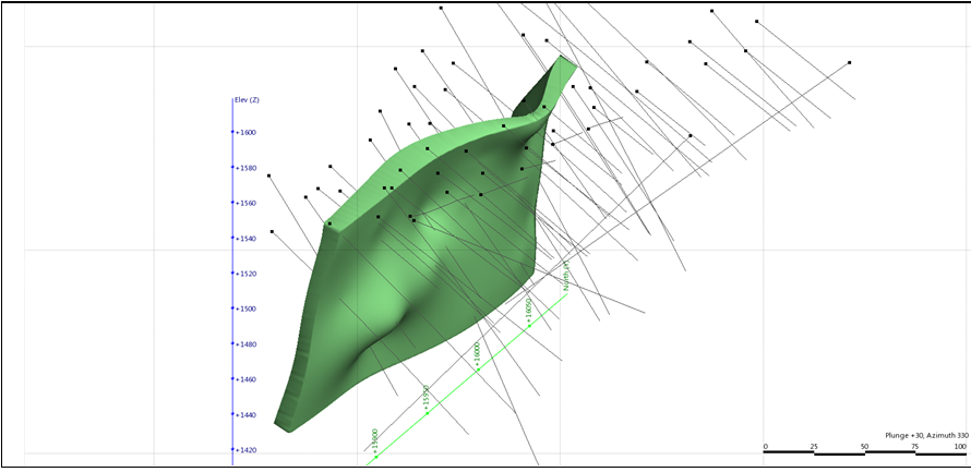
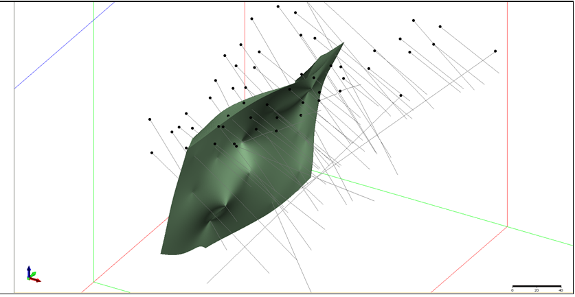 Figure 6. The same vein from the Micromine NVG dataset, Leapfrog using vein modelling (top), Micromine using point cloud modelling of foot and hanging walls and creating a solid from surfaces (bottom).
As you can see the results from both programs are similar, the output generally acceptable, and if not both packages have methods for using the various tools to create the final result you are after. Both programs are capable of using the implicit modelling tools to create a 3D solid geology model. While Leapfrog uses 'Domains' (in the case of LF Mining) or 'Geology Models' (in the case of LF Geo) to create a solid geology model, in Micromine you use the various mesh tools such as Boolean and clipping to edit the results and obtain a final solid model, just as you would a traditional explicit wireframing project.
Additionally as the Implicit Modeller is an integral part of the software it is possible to tie it into the scripting and macro functionality within Micromine so that specific surfaces and models are regenerated every time you update the drillhole database, allowing you to watch various shapes and surfaces evolve with the drilling, similar to using the update drilling options in Leapfrog.
Micromine’s tools are definitely a challenge for ARANZ Geo, the makers of Leapfrog. For those who already own a Micromine licence, the additional cost of the Implicit modelling module is not great compared to the ongoing annual lease demanded by ARANZ Geo. The results are similar and there are a complete set of tools with which to achieve the results you are after. Micromine’s Implicit modeller is early in its development and still has a way to go to match the finesse with which Leapfrog can do some things. Micromine’s method is very resource intensive, when processing it can take up all the computer resources making multi-tasking difficult if not impossible when modelling large datasets and the process is at times marginally slower than a similar task in Leapfrog. Also, whilst it is possible to set a distance buffer to the Micromine’s interpolation the final mesh size on the buffered parts do not match the final mesh of the interpolated parts, leaving the output a little clunky in this area. Additionally, while you can use the mesh editing tools to clip the output wireframes, with complex wireframes this can become a time consuming and difficult task – trying to patch each and every issue to define the final valid product. Being able to do this mathematically by selecting a wireframe solid (say an estimation domain) or DTM (say the topography) to constrain the interpolation when it is run, and have the wireframes merge /clip against the constraining wireframe as part of the interpolation process would be a worthwhile addition. Along these lines would be the ability to automatically push the extents of a surface out to a defined boundary, rather than having the mesh finish at the edge of the data would be a useful feature, although the insertion of a couple of control points does help in this regard.
All in all I think the IM module is a welcome addition to the Micromine package, one that will become better with age.
- This is a fully independent software review by Ron Reid who is employed by Harmony Gold South East Asia and is also a long-time user of Micromine and Leapfrog software products. Ron is not an employee of Orefind, or paid by Micromine or ARANZ Geo. Neither Ron or Orefind receive any benefits from the companies discussed in the Orefind blogs.